
In its simplest form, load testing involves applying a load to a structure or piece of equipment. A proof test is a type of load test that demonstrates the fitness of a load-bearing structure. Such tests may be required as part of a thorough examination in line with Lifting Operations and Lifting Equipment Regulations 1998 (LOLER) that place duties on people and companies who own, operate or have control over lifting equipment.
LOLER places emphasis on the experience of a competent person, who makes an informed decision as to what is appropriate based on their training. They determine if a proof test is necessary or helpful to assess a piece of lifting equipment.
A proof load test is usually expressed as a percentage of the working load limit (WLL) that equipment is designed to withstand.
The exact requirements of proof testing and the extent of each test can vary depending on standards, equipment or industries involved, as well as individual requirements from customers or as part of manufacturers’ own quality controls.
European Standards
Lifting equipment manufacturers may carry out proof tests routinely or as a batch test in line with their own QA/QC procedures, but for goods for sale in the EU a minimum requirement is that of the Machinery Directive.
The Machinery Directive 2006/42/EC section 4.1.2.3 addresses the static and dynamic tests that must be performed on all lifting machinery ready to be put into service. These tests help satisfy the ‘fitness-for-purpose' requirement of lifting machinery or lifting accessories discussed in section 4.1.3. The Directive also states (line 20) that for certain types of machinery having a higher risk factor, a stricter certification procedure is desirable. A few examples of additional certification standards that may require load testing include:
• BS EN 14439: references proof of strength and stability of cranes, including out-of-service stability to account for wind loading.
• EN12079 and DNV2.7-1 standards set minimum criteria for design, material, production and testing of containers used in offshore applications, with specific guidance on proof testing.
• Maritime industries - Proof load testing is required for almost all lifting appliances and loose lifting gear in order to obtain Lloyds Register certification. Other verification bodies such as Det Norske Veritas (DNV) and Bureau Veritas have similar requirements for lifting gear.
Standards for North America
There, proof load testing is performed to meet a number of standards predominantly set out by the following bodies:
• OSHA—Occupational Safety and Health Administration
• ASME—The American Society of Mechanical Engineers
• ANSI —American National Standards Institute
A few examples of standards that may require load tests to be performed on lifting equipment and accessories include:
• ASME B30.9: on lifting slings
• ASME B30.10-1.7: on hooks
• ASME B30.16: on overhead hoists (underhung)
• ASME B30.17: on overhead and gantry cranes and trolleys
• ASME B30.20: various below-the-hook lifting devices
• ASME B30.20: for manual lever hoists
• ASME B30.26: for various lifting accessories: shackles, eyebolts, turnbuckles, links, rings, swivels and compression hardware.
• OSHA Section 1926.251(a)(4) covers special custom design lifting accessories that shall be proof-tested prior to use to 125% of WLL.
• ANSI N14.6: application specific for special lifting devices for shipping containers for nuclear materials weighing >4500kg.
Again, in mission-critical industries, additional tests may be required. NASA for example specifies the occasions and frequency of proof load tests and periodic load tests to be performed on lifting devices and equipment (LDEs) in its NASA-STD-8719.9 technical standard on lifting.
How to proof test?
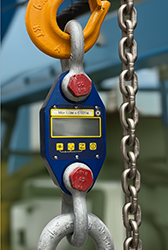
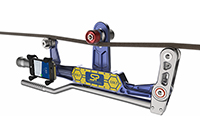
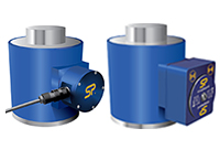
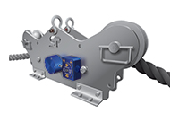
Numerous load-testing applications worldwide require a load cell to verify the load applied, from crane testing using water bags and a tension load link to cylinder testing using a hydraulic test rig and a compression load cell.
A load cell allows the test to be accurately measured and recorded. In safety-critical industries, the requirement to document test procedures and results has never been greater as users of lifting equipment call for more traceability and audit trails.
Proof testing equipment
Crosby Straightpoint manufactures a variety of equipment that can be used for proof testing. As referenced at the outset, its INSIGHT software records data gathered by a Radiolink plus load cell, wireless Load Shackle or LoadSafe wireless compression load cell. It then creates a pass or fail certificate which includes test data and graphs charting data from the load versus time throughout a test.
Information can be printed out directly as a PDF report, electronically transmitted or fed to an information centre in the cloud. It is important that there is traceability of proof test certification and that the load cell that did the test was accurate and calibrated. Where a load test is deemed beneficial the aim of Proof Test plus is to make that process more efficient.
Read more here in our proof testing whitepaper
Why would you choose one over the other?

Getting the right tool for the job is essential
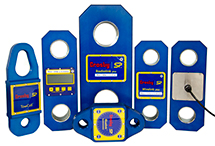
At the simplest level, we could summarise that Loadlinks are for load measurement and Loadshackles are for load monitoring to prevent overload.
Below are some simple criteria to evaluate both options and help you choose the right lifting load cell for your application. At Straightpoint we use the terms ‘loadlink’, ‘dynamometer’ and even 'load indicating device' (LID), they refer to the SP specific name, the generic term and also the term used by ASME B30.26-2010. For the user, there is little or no difference between each.
How they work
First a bit about how they work which will help us understand accuracy.
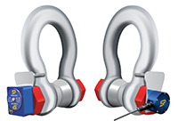
Loadshackles:
Loadshackles work in shear. During manufacturing, SP removes the pin of a standard bow shackle, bore a hole down the middle and bond strain gauges through the centre of the pin. Now, the shackle pin has become a loadpin.
The strain gauges are then aligned with two shear grooves that are visible from the outside of the pin. The groove depth is precisely calculated in terms of position and depth to allow the best Loadpin performance but stay within our strength and safety guidelines. Advanced finite element analysis (FEA) software is used to model and prove our calculations.
The area between those grooves is the ‘load area’. When a load is applied a shear force occurs across those grooves. This shearing effect is measured by the strain gauges which, once the load pin has been calibrated is translated into an actual force or weight reading for the user.
Loadlinks: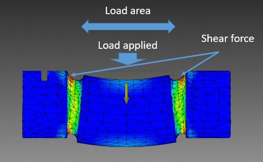
Loadlinks work in tension. Strain gauges are bonded to the body of our aluminium load cells. The process of bonding the strain gauges to the load cell body that is flexing under load is similar to load shackles, but in this case, the strain gauges are flexing directly in line with the pull on the load cell, so straight line and in tension.
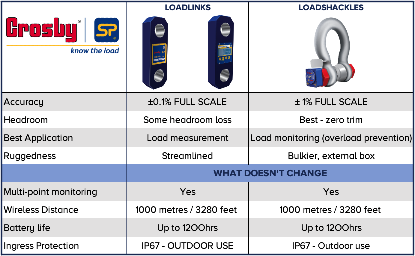
This direct tension force on the body of the load cell while under load gives us a very clear, linear signal from the strain gauges. This is what gives load links superior accuracy of 0.1% full scale vs load shackles at +/- 1% full scale.
To achieve the best accuracy with a load pin it is essential to use the full ‘load area’ as described above. You will notice that Straightpoint Wireless Loadshackles use a bobbin or collar to achieve this
You can read more about the importance of the bobbin in this article here.
Quick guide comparison table
Advantages of SP Loadshackles
- Limited headroom
A loadlink consists of a top and bottom shackle in addition to the height of the loadlink body itself.
As a result, a load shackle typically uses around 1/3 the headroom of a loadlink. - Handling
For those who do mobile testing and carry around load cells with them, a load shackle gives you a one-piece measuring device and especially for heavier capacities this may offer easier handling.
A simple swap to load monitoring
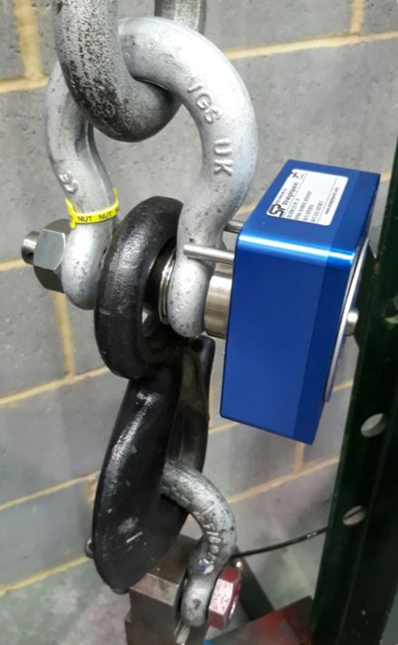
In a rigging setup, it is easy to swap standard shackles for wireless Loadshackles for a simple load monitoring solution. No change in headroom or configuration.
Advantage of SP Loadlinks
- Accuracy
A Loadlink (+/- 0.1% full scale) is around 3 times more accurate than a Loadshackle (+/- 1% full scale).
As such it is often chosen for weighing applications, precise force measurement or to calibrate other devices such as safe load indicators (SLI’s) on cranes.
Advantages of SP Loadlinks and Loadshackles
- Multi-point lift monitoring
Once Loadlinks or Loadshackles are in place the banksman leading the lift has visibility of the individual load on each, as well as the total load from one display, Handheld plus, Bluetooth App or INSIGHT software. It allows them to lead the lift, giving them confidence and control for heavy lifts and when moving bulky or out-of-gauge cargoes. - Wireless distance
The wireless range for both is a leading, reliable, 1000m or 3280ft from loadcell to handheld plus - Battery life
1200hrs battery life for both Loadlinks and Loadshackles - Ingress protection
Both are environmentally protected to IP67
Loadshackles for load monitoring & lifting operations
SP often get asked by customers whether the bobbin on their load sensing shackles can be removed and what are the implications on performance and safety of the loadshackle.
The best way to understand this is to know what the bobbin is, what it does, and why it is important for accuracy, repeatability and safety factor.
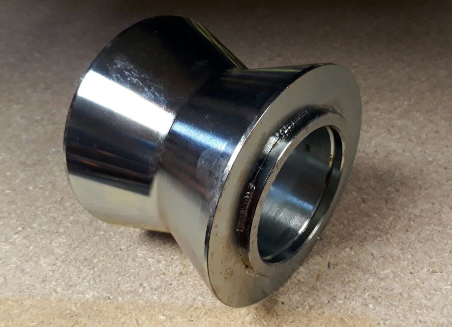
The bobbin design
The bobbin is a metal collar that tapers towards the centre and sits over the (load sensing) shackle pin. Its dimensions ensure minimal lateral play along the pin and its inside dimensions align with the shear grooves on the load pin.

3 things the bobbin does
1. Improves Accuracy
The bobbin spreads the load across the two shear grooves at either side of the load pin as seen below.
It also ensures the full load area is used and that the pin is in a shear, rather than a bending movement.
2. Ensures Repeatability
The taper of the bobbin ensures the load is always applied to the same point.
Any lifting accessories and attachments – slings, chains, hooks, wire rope will naturally pull to the centre of the bobbin, consistently applying the load in one place. This is transferred consistently to the shear grooves by the ‘collar’ effect of the bobbin.
Consistency of load application = repeatability.
3. Safety Factor
The factor of safety is the minimum force the shackle must be able to withstand before breaking. It is expressed as the ratio of minimum breaking load (MBL) to the working load limit (WLL) of the shackle. it is sometimes referred to as the ‘working coefficient’ or ‘safety coefficient’.
Our load shackles have a minimum factor of safety (FOS) of 5:1.
The bobbin ensures this minimum safety factor is met by spreading the load across the pin. In situations where the shackle is subjected to loads far in excess of its WLL it also protects the shackle from ‘closing up’ due to bending of the pin.
Can the bobbin from a load shackle be removed?
A load shackle without the bobbin – like Batman with no Robin!
Having explored what the bobbin is for, let’s return to the original question.
The answer is yes, the bobbin can be removed but it is best to do so knowingly and with good reason.
Know that the load still needs to be applied evenly across the load area and consistently to the same position to get an accurate and repeatable reading.
Know that the safety factor will be reduced, typically to that of a standard load pin which gives a ratio of only 3:1 rather than the usual 5:1.
In certain applications where an alternative collar is available, or where a bracket or lifting eye is manufactured to fit the load pin correctly that is an option.
An alternative of course is for Straightpoint to manufacture a custom made load pin to your application which in some cases will be easier and may give more options and flexibility.
Any other things to know?
Although the bobbin increases accuracy & repeatability significantly (versus no bobbin) it is important to remember that load shackles are more suited to load monitoring and overload prevention rather than weighing and measuring.
For weighing and measurement applications that require the highest accuracy we always recommend a Loadlink or Radiolink.
This email address is being protected from spambots. You need JavaScript enabled to view it.
Rated Capacity or Working Load Limit (WLL)
The maximum load for which the load cell is designed.
Span
Full scale output of the loadcell, usually in mV/V (milliVolts output per Volt excitation or input)
Full Scale Output (FSO)
Load cell output at rated capacity or WLL (full scale),
Usually expressed in mV/V
Zero Output
Load cell output with no load applied.
Expressed as % FSO
Best Straight Line
The straight line between Zero Output and Full Scale Output, used to determine load cell output errors and non-linearity
Non-Linearity
The deviation of load cell output from the Best Straight Line, recorded with increasing loads.
Expressed as % FSO
Hysteresis
The difference in load cell outputs from equivalent increasing and decreasing loads.
Expressed as % FSO
Maximum Error / Combined Error
The maximum error of load cell output from the Best Straight Line, considering both Non-Linearity and Hysteresis.
Expressed as % FSO
Output Symmetry
The difference in FSO from tension operation to compression operation.
Expressed as % Average FSO
Temperature Effect on Zero
The change in zero offset due to a specified change in temperature.
Expressed as % FSO / °C
Temperature Effect on Span
The change in output due to a specified change in temperature.
Expressed as % Output / °C
Creep
The change in FSO occurring over time with all conditions remaining constant.
All materials exhibit creep effects to varying degrees. Load cell creep can be minimised by matching the creep compensation of the strain gauge to the load cell element material used.
Expressed as % FSO / specified time period (usually 20 minutes).
Creep Return
Zero offset after unloading the load cell from a specified time period. Recorded after equivalent time period to which the load was applied.
Expressed as % FSO / specified time period (usually 20 minutes).
Non-Repeatability
The difference in recorded output from successive loadings under constant conditions.
Expressed as % FSO
Excitation Voltage
The safe Voltage used to obtain output values within the quoted specification.
Expressed in Vdc or Vac.
Input Resistance
The electrical resistance of the load cell’s strain gauge circuit, measured across excitation connections with signal connections open circuit.
Expressed in Ohms
Output Resistance
The electrical resistance of the load cell’s strain gauge circuit, measured across signal connections with excitation connections open circuit.
Expressed in Ohms
Insulation Resistance
The electrical resistance measured between the load cell’s strain gauge circuit and the load cell element.
Expressed in Ohms
Primary Axis
The axis of load for which the load cell is intended.